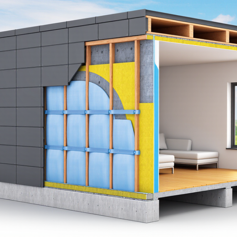
An Insulation Membrane is more than a thin layer hidden behind a wall finish. It can help control heat flow, air leakage, water penetration, and vapor movement. Its position matters as much as its material. A membrane placed on the wrong side may trap moisture, encourage condensation, or reduce insulation performance. Small installation gaps can become large energy losses.
The stakes are substantial. The International Energy Agency reports that buildings consume about 30% of global final energy and produce roughly 26% of energy-related emissions. The 2024 Global Status Report for Buildings and Construction also identifies buildings as responsible for approximately 32% of global energy use. These figures explain why designers increasingly examine complete wall systems, not insulation alone. Still, market claims can be confusing. A membrane is not automatically a cure for every thermal problem.
Joseph Lstiburek, founder of Building Science Corporation, describes the principle clearly: “The perfect wall is a wall that has all of the control layers in the right place.” His observation remains practical on a cold construction site, where a torn sheet, an unsealed lap, or a poorly placed service penetration can undermine the design. The following guide explains how an Insulation Membrane works, where it belongs, and which details deserve closer inspection. Some assemblies perform differently than expected. That uncertainty should encourage testing, not careless assumptions.
An insulation membrane is a thin building layer that controls heat, air, and moisture movement. It does not replace bulk insulation. Instead, it protects insulation from dampness, wind washing, and unwanted air leakage. In a wall, it may sit behind cladding or beneath interior finishes. Its performance depends on continuous sealing around joints, windows, and service penetrations.
Several types are used in construction. Vapor-open membranes allow trapped moisture to dry outward, while vapor-closed sheets limit vapor diffusion in humid conditions. Air-barrier membranes reduce uncontrolled airflow. Reflective membranes can lower radiant heat transfer when installed beside an appropriate air gap. The terminology is not perfectly consistent. That distinction matters.
Standards help define performance. ASTM E96 and ISO 12572 measure water-vapor transmission. ASTM E2178 evaluates air permeability. EN 13859 addresses flexible sheets for roofs and walls. These tests do not guarantee a perfect assembly; installation quality still controls the result. The 2023 UNEP Global Status Report for Buildings and Construction reported that buildings consumed about 30% of global final energy and produced 26% of energy-related emissions in 2022. Better envelopes can reduce this pressure, but membrane selection must match climate, wall design, and drying direction. A vapor-tight layer in the wrong location may trap moisture. That mistake is still common.
How Heat Transfer, Airflow, and Moisture Movement Are Controlled
An insulation membrane is a thin building layer that helps manage heat, air, and moisture. It does not replace bulk insulation. Instead, it supports the whole wall or roof assembly. Heat normally moves through conduction, convection, and radiation. A membrane can slow these paths, especially when it includes a reflective surface and a correctly sized air gap.
Airflow control is often the most noticeable benefit. Small gaps around pipes, joints, and electrical outlets can carry warm indoor air into colder spaces. This movement wastes energy and may deposit moisture inside the assembly. A continuous membrane, sealed with compatible tapes or gaskets, limits these leaks. The work is detailed. One unsealed edge can weaken an otherwise careful installation.
Moisture control requires more judgment. Some membranes resist liquid water while allowing vapor to pass. Others act as vapor barriers and need careful placement based on climate and indoor humidity. In a cold region, vapor may move toward the exterior; in a hot, humid region, the direction can change.
Mistakes happen when one rule is applied everywhere. Inspectors should check laps, penetrations, drainage paths, and signs of condensation. A damp timber surface, peeling tape, or musty cavity deserves attention before the wall is closed. No membrane works alone. Its performance depends on design, installation, ventilation, and regular observation.
An insulation membrane is a thin building layer that helps control heat transfer, air movement, and sometimes moisture. Unlike thick fiber insulation, it often works through reflective surfaces and sealed installation. Its performance depends on the whole assembly, not the membrane alone. A poorly sealed edge can reduce real-world efficiency.
R-value measures resistance to conductive heat flow. Higher R-values generally indicate better insulation, but values can change with temperature, thickness, and installation quality. Emissivity describes how much radiant heat a surface releases. A low-emissivity surface reflects more radiant energy, especially across a clean air space. Without that air space, its reflective benefit may be limited. No metric tells the whole story. Thermal performance also depends on air leakage, compression, fasteners, joints, and moisture. Laboratory results are useful, but field conditions can be less predictable.
Tips: Check the tested R-value and emissivity together. Confirm whether the rating applies to the complete wall, roof, or floor system. Keep reflective faces clean and undamaged. Seal overlaps carefully. Small gaps matter. I have found that installation details often deserve more attention than impressive headline numbers. A membrane may perform well on paper, yet disappoint when dust, trapped water, or open seams interrupt its design. Local climate and professional assessment should guide final material choices.
R-Value, emissivity, and thermal performance are key metrics for evaluating how an insulation system limits heat transfer.
R-value measures resistance to conductive heat flow. Higher values generally indicate better thermal resistance at the same thickness.
Emissivity describes how efficiently a surface emits infrared radiation. Low-emissivity foil surfaces can have emissivity values near 0.03–0.05, while many non-reflective surfaces are approximately 0.85–0.95.
A reflective insulation membrane needs an adjacent air space to reduce radiant heat transfer. Its overall performance also depends on thickness, installation quality, air leakage, moisture, and thermal bridging.
Typical mid-range values shown for common insulation materials. Actual R-value varies with density, temperature, thickness, moisture, and installation conditions.
What Is an Insulation Membrane and How Does It Work?
An insulation membrane is a thin layer that manages air, moisture, and vapor movement around insulation. It does not replace insulation. Instead, it helps the insulation stay dry and perform consistently. A typical wall may include interior lining, a service cavity, the membrane, insulation, sheathing, a weather barrier, and exterior cladding. The exact order depends on climate, wall design, and local building practice.
Sealing is critical. Installers may use compatible tapes, liquid-applied sealants, gaskets, or compression seals around joints and penetrations. Electrical boxes, window frames, pipes, and roof edges deserve careful attention. Small gaps can create drafts, condensation, or hidden heat loss. A common site lesson is that neat-looking work is not always airtight. Testing can reveal problems that visual checks miss. Membranes are used in pitched roofs, flat roofs, exterior walls, floors, and sometimes renovated masonry buildings. Their vapor control must match the assembly, or trapped moisture may cause trouble.
Tips: Keep the membrane continuous. Overlap according to its installation guidance. Press tapes firmly onto clean, dry surfaces. Seal corners before covering them. Check penetrations twice. Avoid mixing untested products. No system is flawless. Even experienced crews may overlook one small opening, so inspection and, where appropriate, air-leakage testing remain worthwhile.
| Building Application | Primary Membrane Function | Typical Installation Layers (Exterior to Interior) | Common Membrane Type | Recommended Sealing Methods | Moisture and Air-Control Position | Indicative Thermal Performance | Important Installation Notes |
|---|---|---|---|---|---|---|---|
| Pitched Roof Cold-Roof Assembly | Limits wind-driven rain, controls air leakage, and helps protect insulation from external moisture. | Roof covering Counter-battens and battens Vapour-permeable underlay Rafters with insulation Vapour-control layer Service cavity Interior lining | Breathable roof underlay Water-resistant and vapour-permeable membrane | Overlap joints according to the product specification; tape or mechanically secure laps; seal penetrations with compatible collars or tapes. | Water-resistive layer above the insulation; vapour-control layer on the warm interior side in heating-dominated climates. | Roof insulation commonly achieves approximately R-30 to R-60 in many high-performance assemblies, depending on climate and local code. | Maintain a continuous ventilation path from eaves to ridge where the roof design requires it. Do not block drainage channels. |
| Pitched Roof Warm-Roof Assembly | Creates a continuous thermal and weather-control layer above or around the structural roof deck. | Roof covering Battens or support system Rigid insulation Roof membrane or sealed sheathing Structural roof deck Interior insulation if required Interior finish | Roofing membrane Air, water, or vapour-control membrane selected for the assembly | Fully bonded or mechanically fixed laps; pressure-sensitive tape; liquid-applied sealant at complex penetrations; sealed perimeter junctions. | The primary vapour-control location depends on climate, insulation placement, and membrane vapour resistance. Hygrothermal design is recommended. | Continuous exterior insulation reduces thermal bridging through rafters. Actual performance depends on thickness, conductivity, and fastener effects. | Protect membranes from ultraviolet exposure when they are not designed for permanent exposure. Coordinate roof penetrations before installation. |
| External Wall Rain-Screen Façade | Stops bulk water and uncontrolled air movement while allowing the wall to manage vapour appropriately. | Cladding Ventilated cavity Water-resistive and air-control membrane Exterior sheathing Stud cavity insulation Vapour-control layer where required Interior lining | Housewrap or wall underlay Vapour-permeable air-barrier membrane | Tape membrane laps; use compatible gaskets or flashing tapes around windows; seal top, bottom, corners, and service penetrations. | Usually outside the sheathing as the water-resistive and air-control layer. Vapour control must be selected for the climate and wall build-up. | Many energy-efficient walls target approximately R-20 to R-30 or higher, subject to local requirements and assembly design. | Install flashing so water drains outward. A drained and ventilated cavity improves drying and reduces cladding-related moisture risk. |
| Masonry Cavity Wall | Reduces rain penetration into the interior wall and supports drainage behind the outer masonry layer. | Exterior masonry Drainage cavity Wall membrane or flashing Insulation Structural masonry or framed backup wall Interior finish | Cavity wall membrane Vapour-permeable water-resistive layer | Seal laps and transitions with compatible tape or sealant; use end dams, back dams, and sealed corner details at openings. | Positioned behind the drainage cavity or integrated with the backup wall. Its vapour resistance should support outward or inward drying as designed. | Insulation levels vary widely; continuous insulation is often used to reduce thermal bridging at masonry supports and structural members. | Keep weep holes open and provide positive drainage paths at the base of the cavity and above windows, doors, and other interruptions. |
| Basement Wall Below-Grade | Resists ground moisture, limits air leakage, and helps protect insulation from soil contact and hydrostatic exposure. | Backfill and drainage layer Waterproofing or dampproofing membrane Foundation wall Rigid insulation or interior insulation Interior air/vapour-control layer where required Interior finish | Below-grade waterproofing membrane Protection board or drainage composite where specified | Heat-welded or self-adhered laps, manufacturer-approved liquid detailing, sealed penetrations, and watertight termination bars where required. | The exterior face of the foundation is often preferred for moisture protection and continuity. Interior vapour control requires careful condensation analysis. | Continuous foundation insulation commonly targets approximately R-10 to R-20, depending on climate and code requirements. | Protect the membrane before backfilling. Provide footing drainage, a suitable drainage plane, and a reliable discharge route. |
| Slab-on-Grade Floor | Blocks soil moisture and soil gas migration while reducing heat loss at the floor perimeter. | Floor finish Concrete slab Vapour-retarder membrane Rigid insulation where specified Compacted granular base Prepared subgrade | Under-slab vapour retarder Low-permeance polyethylene or reinforced membrane | Lap and tape joints; seal around columns, pipes, and service penetrations; connect the membrane to perimeter air or vapour-control details. | Directly beneath the concrete slab, generally above the granular base when the design requires protection from ground moisture and vapour. | Under-slab insulation commonly ranges from approximately R-10 to R-20, with higher values possible in cold climates or high-performance buildings. | Prevent punctures during reinforcement and concrete placement. Repair damaged areas with compatible patches before pouring the slab. |
| Crawlspace Ground and Wall Control | Reduces evaporation from the soil and helps control humidity, air leakage, and soil gases. | Floor finish or exposed ground cover Sealed ground membrane Foundation wall insulation Air-sealed rim joist Ventilation or conditioned-space strategy | Crawlspace ground membrane Durable low-permeance polyethylene or reinforced liner | Tape or seal ground-membrane laps; turn membrane up foundation walls; seal around piers, penetrations, and access doors. | Continuous ground-contact vapour and air-control layer. The crawlspace design should be coordinated with insulation and ventilation requirements. | Wall insulation levels vary by climate; insulating and air-sealing the perimeter is often more effective than insulating the floor above an unconditioned crawlspace. | Remove standing water, address drainage problems, and avoid relying on the membrane alone to correct bulk-water intrusion. |
| Window and Door Opening | Maintains continuity of the wall’s water, air, and vapour-control layers at a high-risk junction. | Exterior cladding Head flashing or drip cap Window or door frame Sill pan or sill flashing Backer rod and sealant Interior air seal and finish | Flashing membrane Self-adhered or liquid-applied transition membrane | Use shingle-style flashing; seal corners and end dams; integrate the sill, jamb, and head membranes with the wall water-resistive layer. | Exterior flashing manages water; interior perimeter sealing controls air leakage. The two lines should be continuous but not create unintended moisture traps. | The membrane itself has little insulating value; its main contribution is preserving airtightness and moisture control around the opening. | Install sill protection before the window or door. Provide an outward drainage path and avoid sealing over intended weep openings. |
| Service Penetrations and Junctions | Preserves the continuity of insulation membranes around pipes, cables, ducts, fasteners, and structural transitions. | Membrane field Penetrating service Compatible gasket, collar, tape, or sealant Support or protection layer where required Interior or exterior finish | Airtightness accessory Preformed collar, flashing tape, gasket, or liquid-applied membrane | Use flexible collars for movement; apply compatible tapes to clean, dry surfaces; use sealant only where it can remain accessible and durable. | The accessory must match the control layer being continued: air barrier, water-resistive layer, vapour retarder, or waterproofing system. | No independent R-value should be assigned. The performance benefit comes from reducing air leakage and preventing localized moisture entry. | Minimize penetrations, provide backing where needed, and inspect seals before they are concealed by finishes or cladding. |

An insulation membrane controls heat, air, and moisture around an insulated building envelope. Its performance depends on correct placement, sealed joints, and compatible materials. A membrane may reduce water entry, but it does not replace drainage or sound installation practice.
Fire performance requires careful reading of the test evidence. A product can show limited flame spread while the complete wall assembly achieves a separate fire-resistance rating. These results are not interchangeable. Test reports may address ignition, flame spread, smoke development, or fire exposure for a stated period. The required classification depends on local building codes, building height, occupancy, and construction type. Small details matter. A staple line or unsealed overlap can change real behavior. No membrane is invincible.
Durability testing should reflect service conditions, not only laboratory comfort. Common evaluations include tensile strength, tear resistance, water penetration, dimensional stability, UV exposure, and accelerated aging. Installers should inspect rolls for damage, keep them away from standing water, and seal penetrations around pipes and windows. A practical site check can reveal loose laps, wrinkles, or exposed sections before they become leaks. Still, accelerated aging cannot perfectly predict every climate. That limitation deserves attention.
Compliance also requires traceable documentation, installation instructions, safety data, and evidence from recognized testing laboratories. Requirements may follow regional standards, approved building codes, or project specifications. Designers should verify the exact assembly, not rely on a membrane datasheet alone. When documents conflict, pause and request technical clarification. It may slow the project, but guessing is worse.
"*" indicates required fields